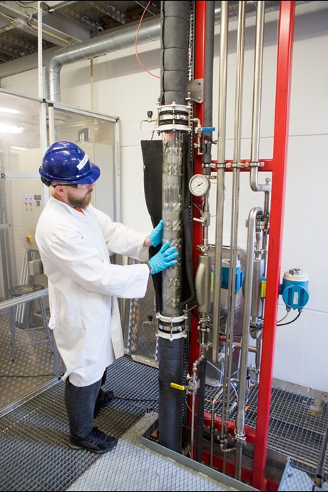
The absorber column consists of 10 glass tubes with a height of 1m each and an inner diameter of 0.1 m. They are connected with flanges, which incorporate a patented liquid sampling system and are equipped with a temperature sensor.
At every second flange there is a liquid inlet, while every other flange has a liquid recollector built in, which transfers the liquid away from the wall towards the center of the column. The height of each glass tube including the flange is approximately 1 m; thus the whole glass section is about 10 m high.
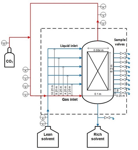
The liquid inlets are at heights of 2, 4, 6, 8 and 10 m height, the liquid re-collectors at heights of 1,3,5,7 and 9 m. Each 1 m glass section is filled with 4 structured packing elements of the type Mellapak 250 Y each with a diameter of 0.084 m and a height of 0.205 m.
The packing elements are fixed with liquid re-collectors inside the glass column, that prevent the gas from bypassing the packing at the wall and which recollect the liquid phase from the wall. The total packed height is 8.2 m and the packing volume is 0.0454 m3.
The distance between the gas and liquid inlet is 10.25 m thus the total column volume is 0.0805 m3.
The differential pressure to the outside atmosphere is measured at the base of the column, the middle (5m) and the column head.

The gas is introduced into the column 0.25 m below the packing with an open-ended pipe. The liquid is distributed into the column with a round spray nozzle with 18 drip points, corresponding to about 1400 drip points per square meter.
The drip points are positioned so that they distribute the liquid uniformly over the cross section. The column has no sump; the liquid is pumped directly into a storage tank.
The glass sections are insulated with 13 mm Thermaflex to limit heat losses during experiments.
The gas system covers the handling of the gas outside the column. In these experiments the gas phase was a closed loop driven by a fan.
Only CO2 was added to the system by gas bottles. The recycle ensures that the gas stream is saturated at the inlet conditions and minimizes CO2 and N2 usage. The gas flow is regulated by the fan speed.
At the column inlet and outlet, CO2 concentration (Vaisala Carbocap), absolute pressure and temperature of the gas phase are measured. A Coriolis flowmeter measures the total mass flow of gas entering the column and another Coriolis flowmeter situated at the gas bottle tracks the amount of CO2 being added to the system.
The liquid is mixed in a 400 L mobile tank equipped with a heating jacket and pumped around with a centrifugal pump. The temperature as well as the mass flow was measured with a PT probe and a Coriolis flowmeter before the liquid inlet.

Scheme and dimensions of DTU’s pilot absorber column setup; red lines indicate the gas system, and blue lines the liquid system.
Publications
T. L. Sønderby, K. B. Carlsen, P. L. Fosbøl, L. G. Kiørboe, and N. von Solms, “A new pilot absorber for CO2 capture from flue gases: Measuring and modelling capture with MEA solution,” Int. J. Greenh. Gas Control, vol. 12, pp. 181–192, 2013.